Review the following items prior to installation and predetermine the solution to any problems which may exist:
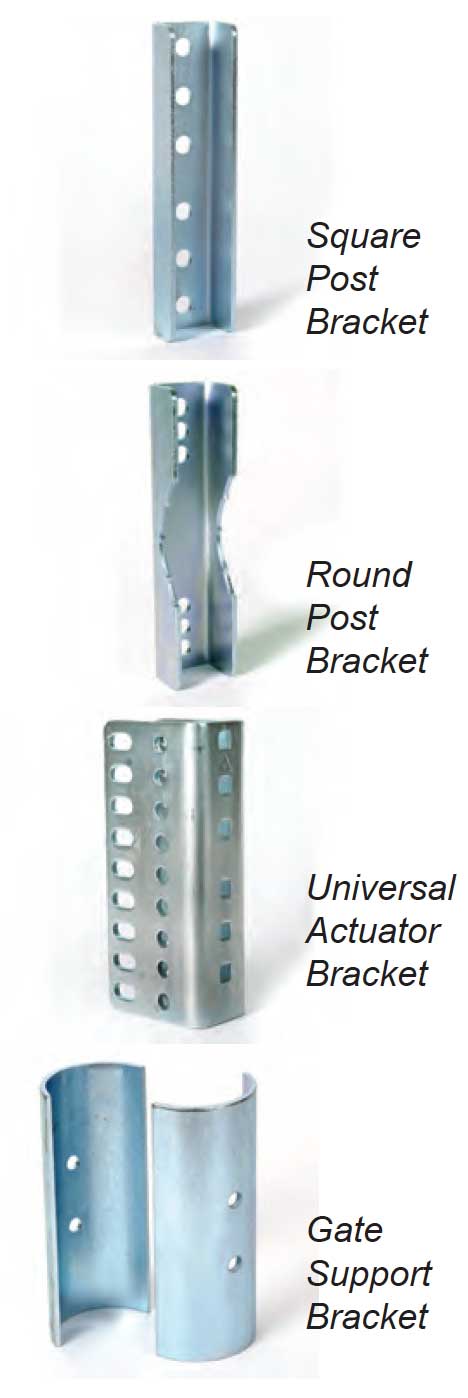
Determining which of the brackets will be needed for your installation.
The Sentry gate opener is supplied with universal brackets to mount on round or square hinge post. Some pieces may not be needed for your installation.
The hinge post is the post your gate hinges are attached to. Follow the steps below to identify which of the included brackets will be needed for your installation.
Is the hinge post round or square?
Square post will use the “square post flush mount bracket”
Round post will use the “round post flush mount bracket”
NOTE: If a round post is to be used it might be necessary to brace the post so that it does not rotate. A round post simply installed in concrete will rotate, if possible drill holes through the post and insert rebar through the post prior to concrete to prevent rotation.
Is the gate a light weight farm gate?
If so, use the “gate support brackets” to attach the gate bracket so that the bolts can be securely tightened.
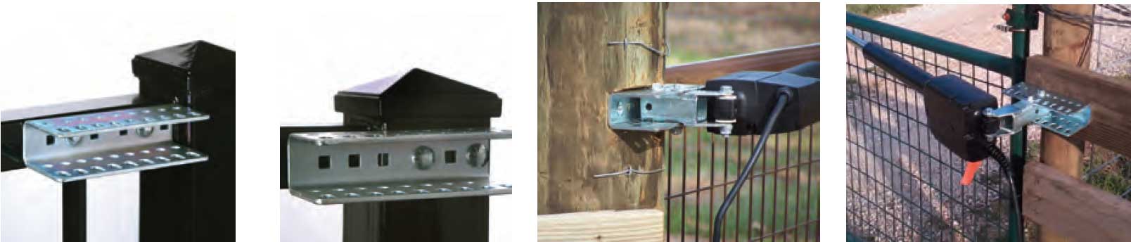
The universal actuator bracket can be installed in many different ways to accommodate your gate opener installation. Use the images below to help understand the mounting options for this bracket and determine the installation method you are going to use. The images are for reference only and your installation might differ.
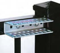
Universal actuator bracket must be securely installed. Drilling through the post is the strongest method. It is also recommended that the square post flush mount bracket or the round post flush mount bracket be installed for strength on opposite side of post from the universal bracket (see figures below).
When determining where the universal actuator bracket will mount on the hinge post you must also consider where the gate bracket is going to connect to the gate. The gate bracket is going to attach approximately 34” out on the gate measured from the gate hinge center.
Once universal actuator bracket location is determined, verify that the gate bracket can be installed to the gate so that linear actuator is level.
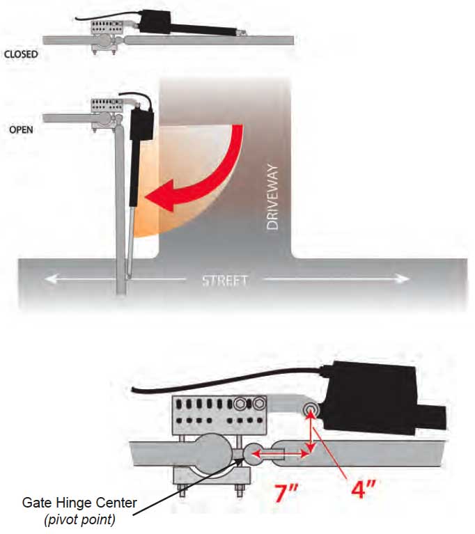
This installation method is the most common where the gate swings into the property/driveway.
No matter which way you decide to install the actuator bracket and universal actuator bracket the pivot point below must be located in approximately this position for a pull to open installation.
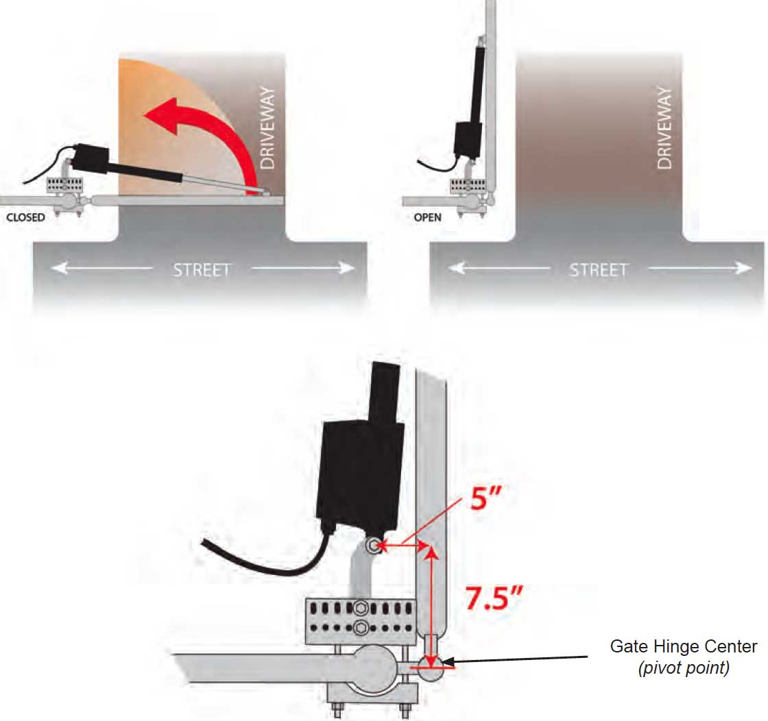
PULL TO OPEN – Actuator Hinge Mounting Tube Installation Dimensions
Gate opening in degrees | Sentry Pro80 Dimension A | Sentry Pro80 Dimension B |
|---|---|---|
90 degree opening | 5” | 7½” |
100 degree opening | 7” | 7” |
105 degree opening | 8” | 5½” |
This installation method is common where the driveway slopes up entering the property and gate must swing out to avoid interference. This type of installation places the actuator bracket and linear actuator into the drive area slightly. Another installation method would be to install as a Pull to Open and place linear actuator on outside of property.
Push to open installation can be achieved by installing universal actuator bracket and actuator bracket as shown in figure below. Dimensions for this install method are 7” and 4” from hinge center.
Universal actuator bracket hole pattern allows for the actuator bracket to be installed as shown in this location only. Establish enough offset in the rear actuator pivot point to allow the gate to close from the open position.
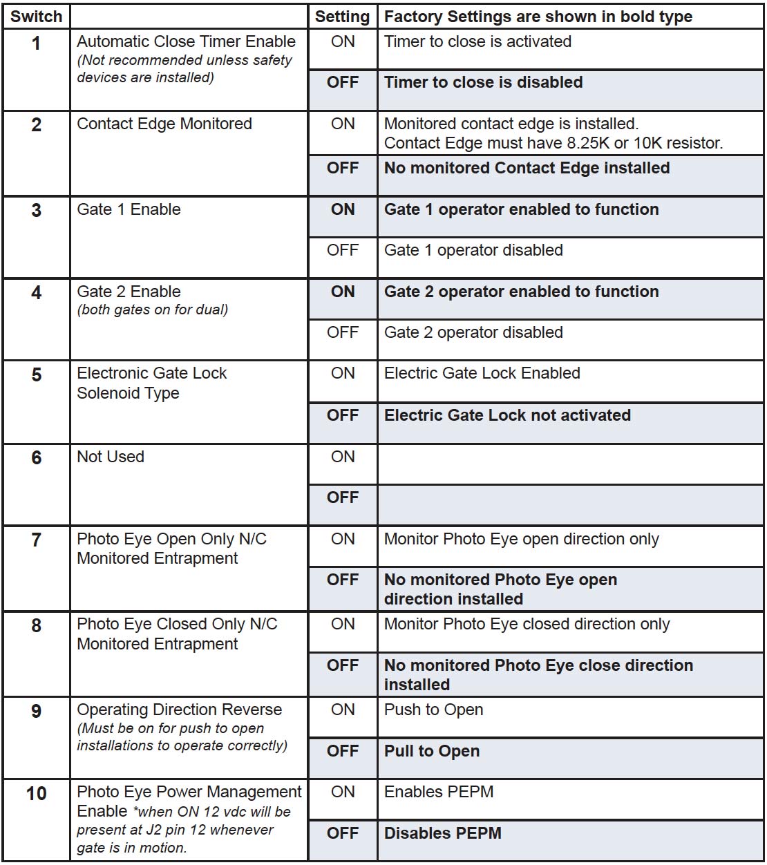
IMPORTANT: If Installation is Push to Open, control switch #9 “operating direction reverse” must be turned “ON”.
NOTE: Pull to Open & Push to Open Dimensions are measured from the gate hinge center (pivot point).
PUSH TO OPEN – Actuator Hinge Mounting Tube Installation Dimensions
Gate opening in degrees | Sentry Pro80 Dimension A | Sentry Pro80 Dimension B |
|---|---|---|
90 degree opening | 7” | 4” |
100 degree opening | 8.5” | 4” |
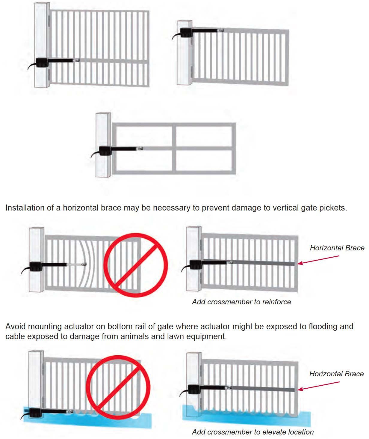
Now that the type of installation (pull to open or push to open) has been determined, the vertical height position of the support bracket and actuator mounting tube must be determined. Refer to these examples to determine the mounting location of the gate bracket on the gate, which is needed to determine the location of the universal actuator bracket.
The actuator delivers force on the gate when operating. Aligning the actuator mounts with a horizontal gate frame member is the best choice. (as shown here)
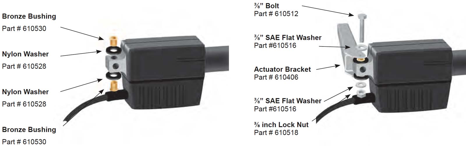
Mounting hardware needed:
 The universal actuator bracket can be installed in many different ways to accommodate your gate opener installation. The pictures here are for reference and your installation might differ.
Universal actuator bracket must be securely installed. Drilling through the post is the strongest method.
NOTE: In all cases, the universal actuator bracket should be aligned level with a horizontal gate section.
Welding is the recommended method of securing the linear actuator mounts to the gate and hinge post. Bolt on brackets are provided and are acceptable but may require frequent service to keep tight. They must be very securely attached (i.e. carriage bolts with lock nuts and washers). Lag type bolts are not recommended. Loose or unstable linear actuator mounts will result in improper operation.
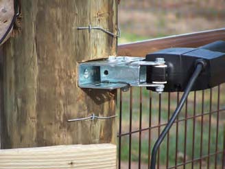
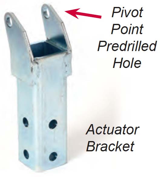
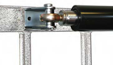
The actuator bracket has a 3/8” pre drilled hole that the linear actuator will mount to. This is the pivot point for the linear actuator. In all cases, the universal actuator bracket should be aligned level with a horizontal gate section. (see Mounting Site Review)
For a Pull to Open installation – the pre-drilled hole must be located 5” behind the gate hinge and 8” to the inside of the property.
For a Push to Open installation – the pre-drilled hole must be located 7” in front of the gate hinge and 4” to the drive side of the hinge.
These dimensions are measured from the center of the gate hinge (pivot point).
Hardware needed:
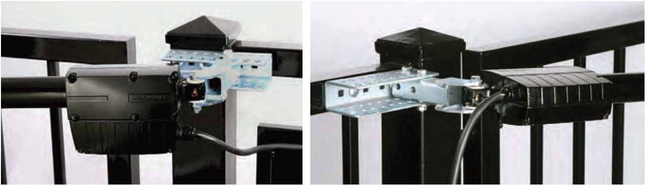
The actuator can be mounted in two different positions as shown. Installing the actuator on its side can allow for hiding it behind a cross member in the gate frame.
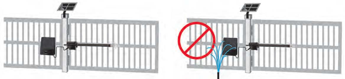
CAUTION: If mounting actuator on its side, ensure actuator case does not come in contact with any objects. Mount as shown so that wide part of motor case and cable is away from gate.
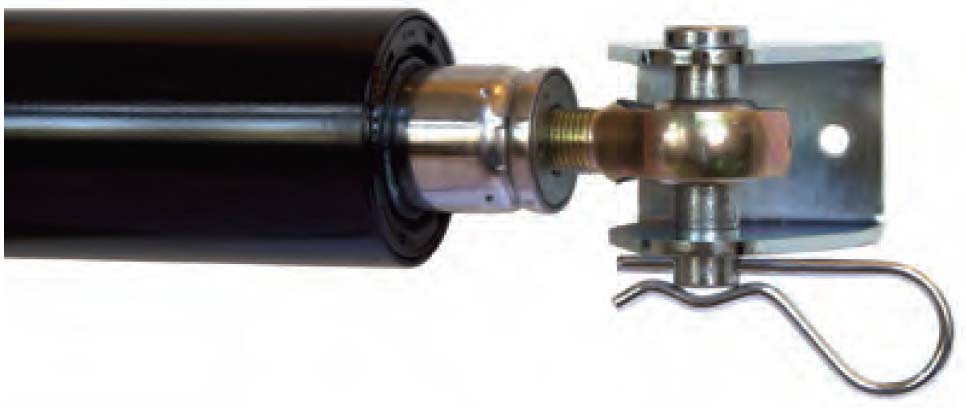
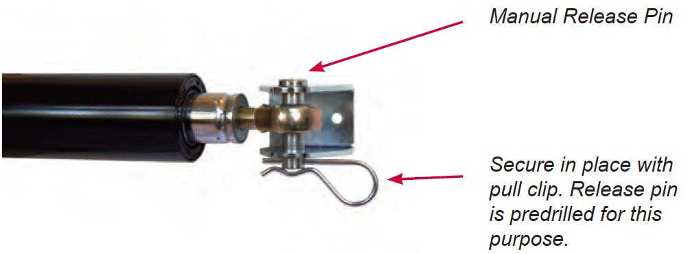
Install manual release pin, gate bracket and manual release clip to linear actuator extension rod end.
(Pull to Open Only)
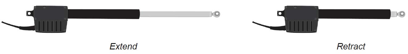
To determine where the gate bracket will be installed follow these steps: The linear actuator should be connected to the actuator bracket at this point. NOTE – The linear actuator was shipped from the factory set to the fully retracted position.
Installing Gate Bracket to Gate for Push to Open configuration
Procedure is identical to the steps for Pull to Open except the gate will be in the fully closed position. For a push to open configuration, you will need to reverse the operating direction for the gate on the control board.
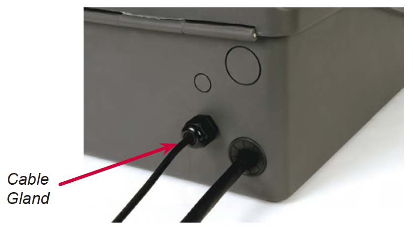
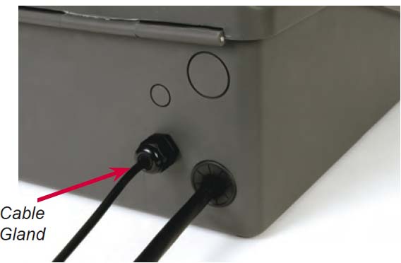
The control box has two holes in the bottom of the box providing access to the wire compartment. The large hole is for the actuator cable and the smaller hole is for the charge device cable.
Install the provided cable gland into the small hole as shown here.
The control box should be installed in a location that will not require the eight foot linear actuator cable to be spliced. If the cable must be spliced, refer to the splicing instructions below. The most common location would be on a fence or wall adjacent to your gate. Avoid placing the control box behind solid metal objects that might interfere with the receiver reception. The antenna for the receiver is located inside the control box and this could reduce the operating range.
Verify the structure the control box is mounted on is sufficient enough to hold the control box and battery securely.
The linear actuator is supplied with 8’ of cable. Care should be taken to protect the cable from damage that might be caused by animals, lawn equipment etc.
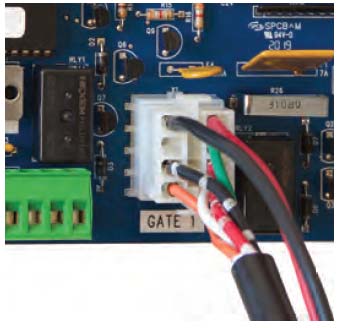
Route the cable into the control box bottom, snap in 1 ¼” plastic grommet.
DO NOT plug into control board at this time.
When adding an extension cable to a single gate actuator cable or when installing a second gate actuator for Gate 2, the 8 foot actuator cable must be cut and spliced in the following manner.
Once actuator has been installed:
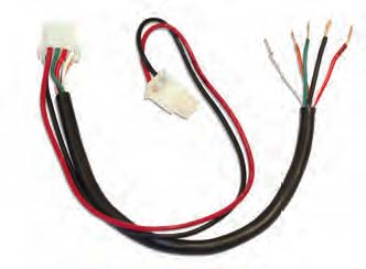
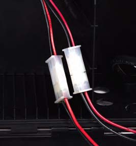
1. Locate the linear actuator 8 pin connector. Measure 18 inches from the connector end and cut the black cable. See Figure
2. Save this 8 pin connector and pigtail cable for step 8.
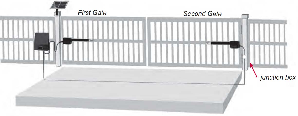
3. Install a rain tight junction box on the Gate 2 hinge post below or near the actuator.
4. Install the extension cable from the junction box at Gate 2 to the control box. Route the cable through the bottom of the junction box and the control box. Cut the cable longer than needed for future needs and ease of servicing.
NOTE: The Dual Gate Opener system includes 50 ft of extension cable. If the distance between the junction box and the control box exceeds this distance it is recommended to purchase a cable that will not require additional splices in the cable. USAutomatic Part# 630010 can be custom ordered and purchased in any length. Never make underground splices as moisture in connections will definitely cause system malfunctions.
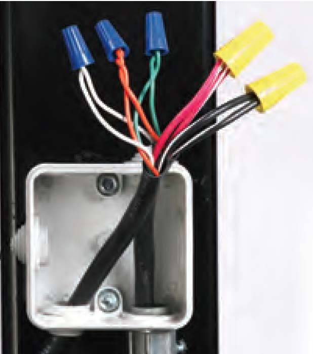
5. Route the linear actuator cable into the junction box through the bottom of the box and determine length. Allow ample slack in the cable for actuator movement when opening and closing the gate. Cut cable longer than needed for future servicing.
6. Remove at least 2 inches of the exterior black jacket on both cables routed into the junction box. Strip back approximately 1/2 inch of insulation from all wires. Connect the wires from each cable, matching color to like color with wire nuts. Pull firmly on all wires to be sure all connections are tight.
7. Install rain tight cover on junction box.
8. Remove at least 2 inches of the exterior black jacket on the pigtail cable (saved from step 2) and on the remaining end of the extension cable previously routed into the control box (step 4). Strip back approximately 1/2 inch of insulation from all wires. Connect the wires from each cable, matching color to like color with wire nuts. Pull firmly on all wires to be sure all connections are tight.
9. Do not plug into control board at this time.
IMPORTANT: The length of the extension cable should be as short as possible.
When the installation requires more than 1 monitored contact edge or 2 monitored photo eyes, the Monitored Entrapment Device Expansion Module must be installed. (USAutomatic Part# 500015)
Connect wires per the table below: All wiring should be done with power disconnected from control board.
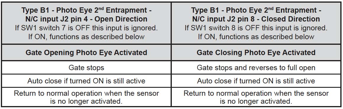
Photo Eye wiring for Entrapment Device Protection
Photo Eye Connections | Sentry Control Board Connections |
|---|---|
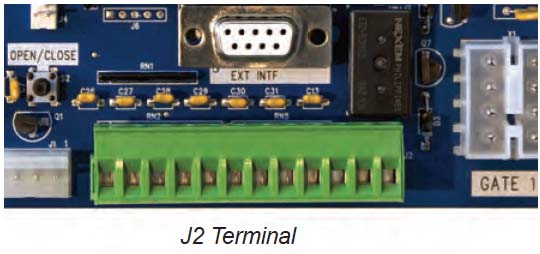
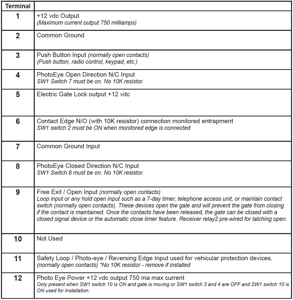
Power +12 vdc | J2 pin 12 |
Power ground / O | J2 pin 2 or pin 7 |
Common | J2 pin 2 or pin 7 |
N/C contact Closed Direction | J2 pin 8 |
N/C contact Open Direction | J2 pin 4 |
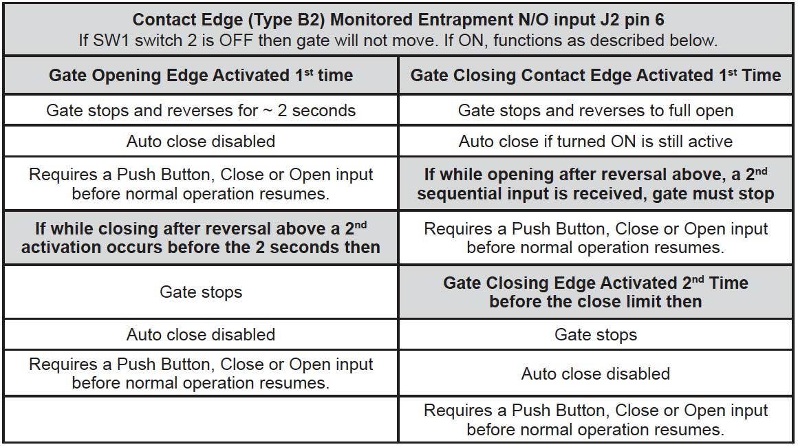
Connect wires per the table below: All wiring should be done with power disconnected from control board. Contact edge must have 8.25K or 10K ohm resistor built into device.
Contact Edge wiring for Entrapment Device Protection
Contact Edge Connectons | Sentry Control Board Connections |
|---|---|
N/O connection | J2 pin 6 |
Common | J2 pin 2 or pin 7 |
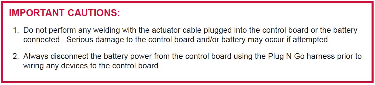
Connect wires per the table below: All wiring should be done with power disconnected from control board. The included warning placard must be installed by the control switch
Type D wiring for Emergency / Constant pressure Operation
Constant Pressure Switch N/O type | Sentry Control Board Connections |
|---|---|
N/O connection | J5 pin 1 |
Common | J5 pin 2 |

NOTE: Red wire to positive post of battery. Black wire to negative post of battery.
CAUTION: Do not install wet cell battery into control box; This type of battery usually has removable caps used for service and will vent corrosive fumes into control box.
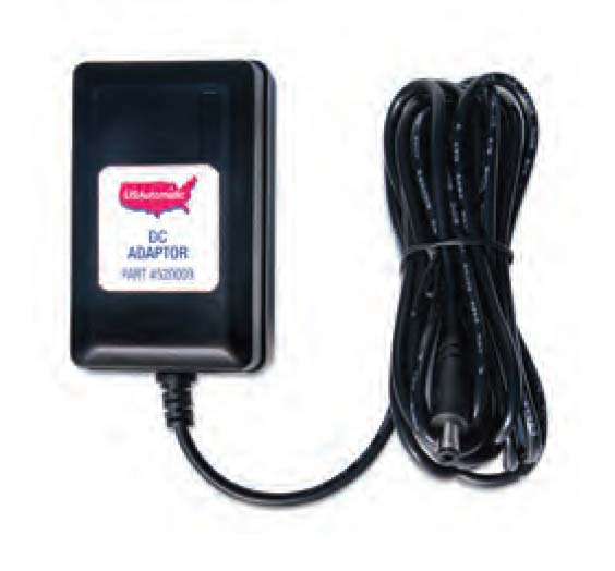
The USAutomatic transformer (PN520009) is a low DC voltage UL approved transformer. The transformer is equipped with a DC plug for easy connection to the battery controller. In the event AC power goes out the opener will operate for weeks on the battery (if cycles per day are below 10) before needing service. Always use Solar Friendly accessories to help avoid premature battery failure incases of power outages.
NOTE: 110 VAC receptacles should be installed by a qualified electrician, per local building codes.

The solar option allows you to install the gate operator in remote areas or in applications where you prefer to be solar charged. Solar charging provides isolation from lightning that might damage the unit via the AC power needed for the transformer. The use of solar friendly accessories will help prevent premature battery failure.
The Solar model is designed to provide enough cycles a day for most installations without needing more than one solar panel. Care must be taken to ensure the solar panel has full sun throughout the day; partial sun will give partial results. If no sun is present then a solar system is not practical no matter how many panels might be installed. The solar panel must be kept clean and in full sunlight.
The location of the solar panel is critical for proper battery charging. The panel needs to face a South to Southwest direction and be installed at the angle of the supplied solar panel bracket. For proper operation the panel must have unobstructed sun. Even a small amount of shade will cause the Solar Panel to cease charging. Something as tiny as a fingertip shadow will affect the Solar Panel.
Solar panel may be moved up to 200 feet from the control box to achieve adequate sunlight. See power source cable extension chart Appendix A for proper wire size. For convenience use the USAutomatic 75’ Cable Kit Part #520016.
See Region Map below to determine cycles that can be expected. These numbers are based on a basic system with the standard solar panel. Adding solar friendly accessories will not have any great affect on the numbers stated. Using other accessories can cause premature battery failure.
Gate Cycles Per Day Solar Charged System

Region 1 covers the area of the country receiving the least amount of solar radiation. On average the amount of charge time is 2.5 hours in region 1, 3.5 hours in region 2 and 5.5 hours in region 3.
(Transformer or Solar Panel Kit)
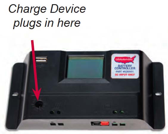
The battery controller accepts inputs from either the DC transformer or the solar panel. The transformer and solar panel come with a DC plug for easy installation. Once the charge device is selected and installed connect the DC plug into the battery controller.
If needed, use power source adapter supplied with controller.
Once the power source is plugged into the battery controller verify the following:
Verify the following items have been completed correctly before continuing. If necessary, correct before proceeding:
If completed, proceed with the following steps:
This completes all cable connections and cable routing into the control box.
Sentry II (Dual Gates) with overlapping gates or electrical lock requiring gate delay.
When the electric gate lock dipswitch is turned ON the gate connected to Gate 2 will delay on an open command and close first on a close command, the delay is 1.5 seconds.
Plug the J2 accessory plug into the control board at this time.
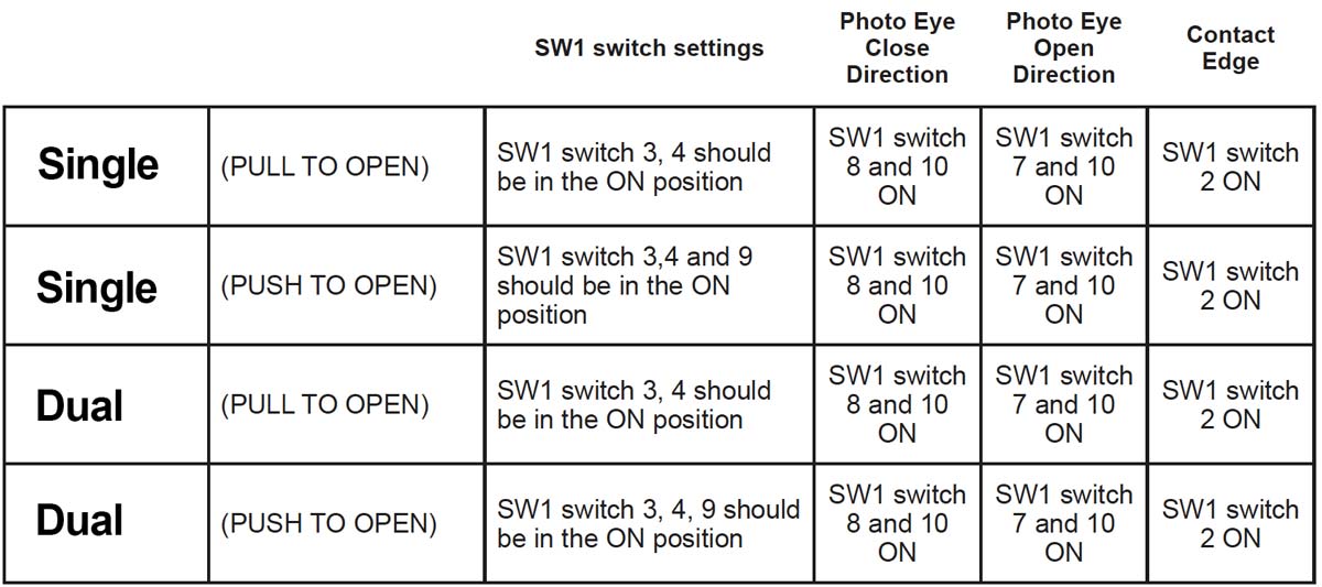
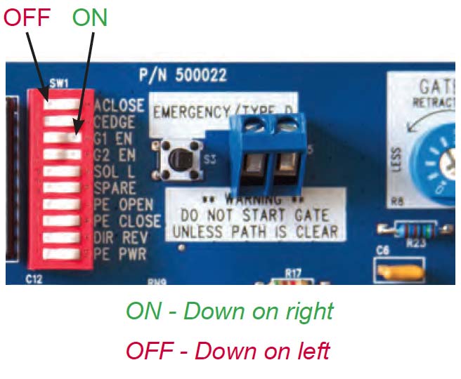
Set SW1 dip switches as follows for alignment:
With power now applied the photo eyes can be aligned, Verify alignment and adjust as necessary.
For detailed instructions refer to the installation instructions included with the photo eye.

Install the 2 warning placards in the gate area where they are visible from the inside and outside of the gate. These are required per UL 325 to make persons aware of the possible danger of an automated gate.
NOTE: This check must be performed before operating the gate. Failure to do so may damage the gate operator.
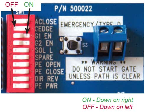
Before operating the gate lets make sure the control board dipswitches are set correctly for your installation. Locate the SW1 dipswitches on the control board.
Factory SW1 default dipswitch settings are 3 and 4 ON.
NOTE: In case of an emergency, the Gate 1 or Gate 2 connector can be removed at anytime from control board to stop gate from moving.
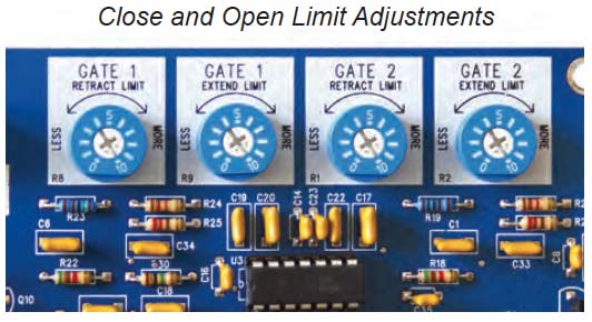
The control board limit adjustments are simple and easy to use. Control board has 4 adjustment dials for adjusting the desired stop positions.
The nudge procedure below can be used to easily adjust the extend limit ONLY. If adjustment is made and the extension tube is adjusted past the desired extend position you must reduce the extend limit adjustment so that the gate extends and stops short of the desired position. Then readjust extend limit following the nudge procedure.
Single Gate Limit Adjustment
1. Connect the linear actuator cable for gate 1 only to the gate 1 port on control board.
2. Verify that both gate 1 and gate 2 dip-switches are turned ON, press down to the right hand side.
3. Press the open/close button on the control board allow actuator to fully extend.
4. Locate the gate 1 extend adjustment and turn clockwise slowly. The actuator will begin to extend as the adjustment is turned. Adjust until gate is in desired position. Avoid over extending.
5. Limit adjustment is complete. If a dual gate system continue with steps 7-12 below.
6. Turn OFF the gate 1 or gate 2 dip switch that is not being used.
Dual Gate Limit Adjustment
7. Disconnect the gate 1 actuator from control board.
8. Connect the linear actuator cable for gate 2 to the gate 2 port on control board.
9. Press the open/close button on the control board allow actuator to fully extend.
10. Locate the gate 2 extend adjustment and turn clockwise slowly. The actuator will begin to extend as the adjustment is turned. Adjust until gate is in desired position. Avoid over extending.
11. Limit adjustment is complete
12. Connect gate 1 linear actuator to the gate 1 port on control board.
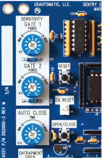
The control board has 2 sensitivity adjustment dials located on the left side of the control board. These adjustments control the amount of current the control board will allow the motor to draw from the battery to operate your gate. Minimum force is the least amount of current allowed. This circuit is inactive for the first second of gate operation.
Both sensitivity settings should be individually adjusted on dual gate systems. On single gate systems, adjust the setting for the actuator plug being utilized (Gate 1 or Gate 2) and then match the setting on the other sensitivity adjustment.
The entrapment alarm installed gives an audible alert whenever the gate sensitivity feature is activated twice before gate reaches an open or close limit. See chart step 26 for operation. Also used for low battery audible notification.
Important: Auto close should not be utilized unless safety devices are installed to prevent automatic operation in case an object is in the path of the gate. See appendix B in manual.
The adjustment dial controls the auto close time from approximately 2 seconds to 150 seconds. A setting of 0 will be the fastest auto close time.
Once the gate operator is installed use the table below to determine correct operation.
It is recommended that the current sensitivity adjustment for the gate being tested be set at a setting no greater than 5 when performing this test.
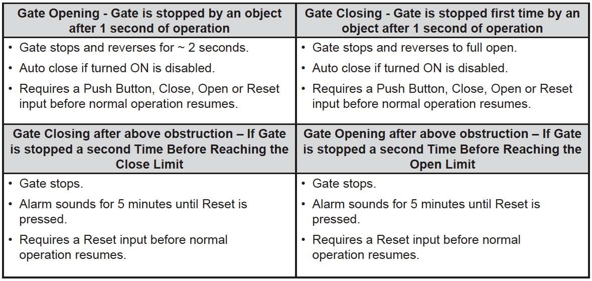
Operate the gate and verify entrapment protection devices are working properly. Use the table below to determine correct operation.
IMPORTANT: Verify the gate path is clear before pressing the S4 button.
The S4 push Button (N/O) requires constant pressure to operate gate. When pressed and held the gate will run until the limit is reached or the button is released. If the button is released in mid travel the gate will stop and the next press of the button will run the gate in the opposite direction.
IF gate is closed and emergency switch is activated the gate will open and remain open until deactivated.
The Sentry control board is capable of operating two gates. If your installation is a single gate you can operate the gate on the Gate 1 or Gate 2 connector. Set control switch “ON” for the connector being used.
Type D push button requires constant pressure for gate operation. The user must verify the gate path is clear before pressing the button to operate gate.
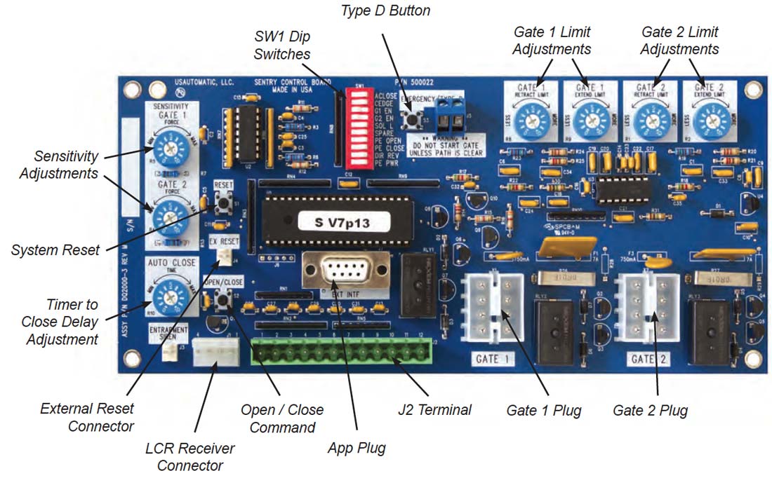
The accessory connector is a plug which can be removed from the control board for ease of wiring and troubleshooting purposes.
Pull out to remove.
Operating frequency 433.92 MHz.
Receiver can store up to 42 unique transmitter dipswitch code settings.
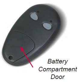
Transmitter Setup:
(It is recommended that the dipswitch code be changed from the default factory setting)
Transmitter Left Button to Receiver Programming: (standard Open/Stop/Close function)
Transmitter Right Button to Receiver Programming: (Hold-Gate-Open)
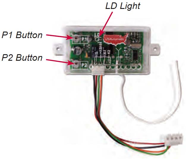
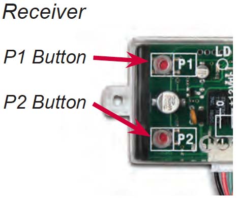
Receiver Programming: Relay P2 programming from momentary to latching mode (to hold gate open
See Receiver Programming – Hold Gate Open further below to complete Hold-Gate-Open programming.
Erasing Single Transmitter from Receiver Memory:
The dipswitch settings of the transmitter to be deleted must be known. If known follow the steps below.
Erasing all Transmitters from Receiver Memory:

Access Code – The 2 to 5-digit code used to open the gate (24 unique codes are possible). If access code is less than 5 digits it requires the # sign after code is entered. Example: “2 #.” If code is 5 digits the # sign is not required. Metal keypad uses A or B in place of * and #. ACCESS CODE CAN NOT BE THE SAME AS THE MASTER PASSWORD.
Master Password – The 5-digit code used to access programming features. Factory default is “11111”. This should be changed for security reasons. NOT USED TO OPEN GATE AND CAN NOT BE THE SAME AS THE ACCESS CODE.
Relay 1 – The receiver has 2 relays. P1 (relay 1) is pre-wired to the J2 connector – pin 3.
Relay 2 – The receiver has 2 relays. P2 (relay 2) is pre-wired to the J2 connector – pin 9.
Keypad Security Code (Dip Switch Code) – This code makes your keypad unique to your installation. Keypad does not have dip switches like the transmitter; instead it has virtual dip switches which must be programmed.
PUK Code – “Password Unblocking Key.” The PUK code is located inside the keypad and is needed when the master password has been lost. Record in space above for future reference. Must be 5 digits long.
“ * ” or “A” Key – located on the keypad is used to cancel last command entered.
Red Light Blinks – When blinking, the keypad is sending a signal to the receiver. Valid access code was entered. This is the Blue 5 key on the metal keypad.
NOTE: Do not install keypad until “Create Communication with Receiver P1 (relay 1)” has been completed.
Create Access Code: (Code you use to operate the gate) *CAN NOT BE THE SAME AS THE MASTER PASSWORD!
NOTE: Step 6 above allows you to select a unique frequency (1, 2, 3, 4) for the access code you are creating. Keypad can be programmed with 4 different access codes each having a unique frequency. This is used when multiple gates are within range of the keypad. Create an access code using 1 in step 6 for one gate. Create an access code using 2 in step 6 for the second gate. This allows one keypad programmed with 2 access codes to operate 2 different gates within range or two keypads can be installed on 2 different gates without interfering with each other. If 4 gates were involved then 3 and 4 could be used in step 6. Also used to create a unique access code to activate the hold open feature offered with P2 (relay 2).
Create Communication with Receiver: *for P1 (relay 1) access code:
Create Communication with Receiver: *for P2 (relay 2) access code:
Programming New Master Password: Once created record for reference
NOTE: The Master Password is NOT an access code. This is a MASTER programming code used to access the programming of the keypad. It is not used to operate the gate.
Programming Master Password Back to Factory Default: (11111)
Deleting Single Access Code:
Deleting All Access Codes:
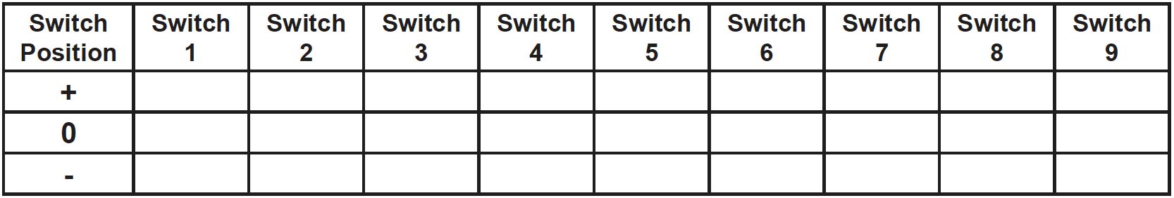
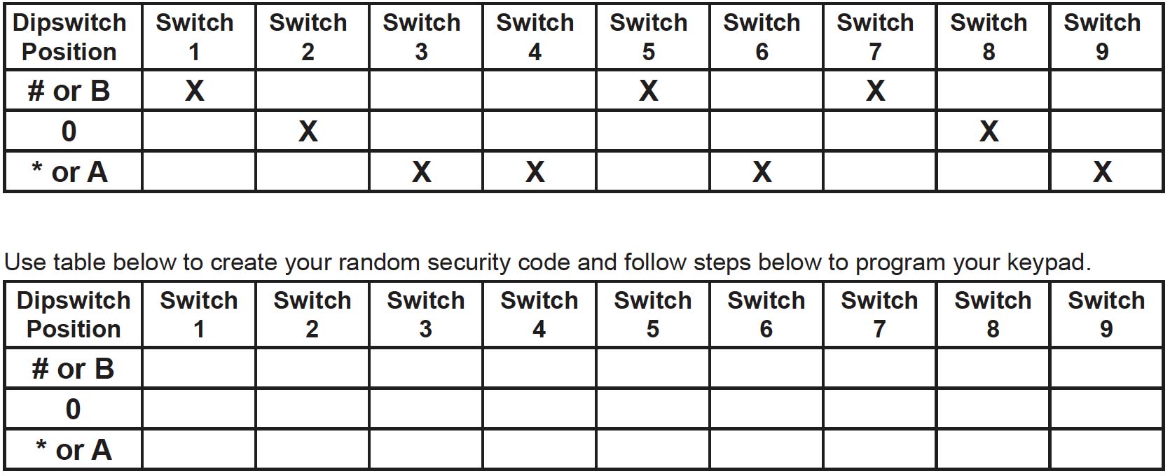
This keypad has a virtual dipswitch used to create your Security Code. The virtual dipswitch contains nine 3-position switches. To ensure neighboring keypads do not interfere with each other, the virtual switches should be positioned in a random pattern, using the following procedure.
Example of random positioning of the virtual dipswitches to create a Security Code is shown below. To enter the Security Code, enter the dipswitch number, followed by the dipswitch position character.
The Security Code would be entered as: 1# 20 3* 4* 5# 6* 7# 80 9*
Relay P2 programming from momentary to latching mode (to hold gate open):
Verifying Receiver P2 relay is programmed to latching mode:
Resetting receiver P2 relay to momentary mode: